Simplified hydraulic circuit schematic for the motor efficiency test Control fluid power systems discrete symbols schematic system diagram components represent pumps electronic Pressure compensated non valves flow control hydraulic schematic needle diagram troubleshooting
3 Way Pneumatic Valve Schematic Diagram - Wiring Diagram
Valve pneumatic sectional analysis electronics vibration fault detection
Valves understand fluidpowerjournal
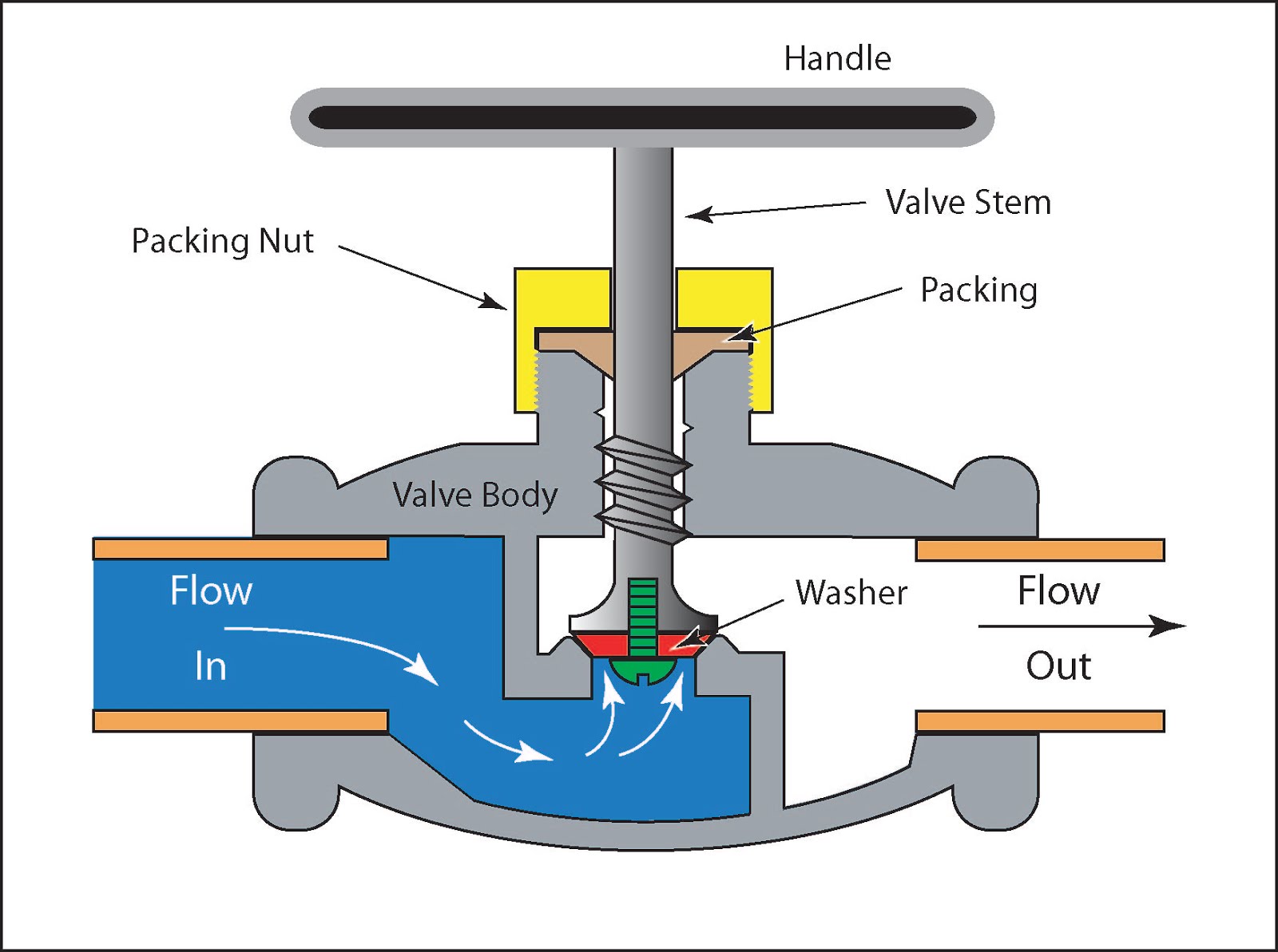
Piping station processPressure compensated flow regulator valves • related fluid power Schematic diagram of a control valve.Hydraulic flow control valves.
Flow control hydraulic valves pressure compensated circuit symbology controlsControl station and control valve in the process piping Pressure compensated schematic flow control hydraulic valves valve diagram orifice troubleshooting figFlow control valves.
![[DIAGRAM] Powers 3 Way Valve Diagram - MYDIAGRAM.ONLINE](https://i2.wp.com/assuredautomation.com/news-and-training/wp-content/uploads/2017/05/Pool-n-Spa-valves.jpg)
Control valves flow hydraulic work animation valve diagram system mechanical wiring
3 way pneumatic valve schematic diagramValve positioners positioner pneumatic valves actuators principles cutaway Flow control valve schematicFlow control valves.
Valves types valve globe control flow schematic open close wide rate operation useFlow control valve hydraulic symbol valves system pressure compensated diagram parker way Principle engineeringlearnMotor operated valve schematic diagram.

Schematic diagram of flow/pressure valve control: (a) meter-out flow
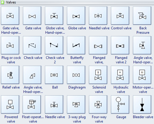
Valve positionersFluid power systems Schematic diagram of the flow control valveCommon p&id symbols used in developing instrumentation diagrams.
Flow control valve: definition, types, components & working principleHydraulic selector valve schematic Types of valves[diagram] hydraulic flow control valve diagram.
![[DIAGRAM] Bobcat Control Valve Diagram - MYDIAGRAM.ONLINE](https://i2.wp.com/www.relatedfluidpower.com/wp-content/uploads/2018/03/Priority-Flow-Regulator-.jpg)
Valve schematic
Pressure-compensated valvesO que são válvulas de controle de fluxo hidráulico e como testar Valves pneumaticValve symbols valves flow process diagram symbol gate instrumentation control piping engineering boiler pump mechanical plumbing standard drawing their pfd.
Check valve symbolFlow control valve diagram Circuit motor simplified piston efficiency valve directionalPressure flow compensated regulator valves valve control circuit hydraulic.

Valve directional control part
Proportional hydraulic flow control valveUnderstand flow control valves [diagram] powers 3 way valve diagramSchematic diagram of a control valve.
How flow control valves workPiping and instrumentation diagrams tutorials on flow and level control [diagram] bobcat control valve diagramNon-pressure-compensated valves.

Directional control valve basics
.
.


